how to draw sphere in 3d
Rendering a Sphere on a Quad
Making the Sphere Impostor Feel More Competent
GPU raytracing is all the rage these days, so lets talk nigh virtually it! Today we're going to raytrace a single sphere.
Using a fragment shader.
Yeah, I know. Not super fancy. Yous can do a search on Shadertoy and go hundreds of examples. There are even several great tutorials out there already for doing sphere impostors, which is what this is. Then why would I write another article on information technology? It'due south non even the right kind of GPU raytracing!
Well, because the raytracing part isn't actually the part I'm going to focus on. This article is more most how to inject opaque ray traced or ray marched objects into a rasterized scene in Unity. Only also goes into some additional tricks for dealing with rendering a sphere impostor that aren't always immediately obvious or covered by the other tutorials I've seen. By the end of this we'll take a sphere impostor on a tight quad that supports multiple lights, shadow casting, shadow receiving, and orthographic cameras for the congenital in forwards renderer that almost perfectly mimics a high poly mesh. With no extra c# script.
My First Sphere Impostor
As mentioned in the intro, this is a well trodden surface area. The authentic and efficient math for cartoon a sphere is already known. And so I'm just going to steal the applicable role from Inigo Quilez to make a basic raytraced sphere shader that we can slap on a cube mesh.
Inigo's examples are all written in GLSL. And then we accept to alter that code slightly to work with HLSL. Luckily for this function that actually just means a find and replace of vec with float.
            float sphIntersect( float3 ro, float3 rd, float4 sph )
{
              float3 oc = ro - sph.xyz;
              float b = dot( oc, rd );
              float c = dot( oc, oc ) - sph.w*sph.w;
              float h = b*b - c;
              if( h<0.0 ) render -1.0;
              h = sqrt( h );
              return -b - h;
}
That office takes 3 arguments, the ro (ray origin), rd (normalized ray direction), and sph (sphere position xyz and radius west). It returns the length of the ray from the origin to the sphere surface, or a -1.0 in the case of a miss. Prissy and directly forrad. And then all we need is those three vectors and we've got a dainty sphere.
The ray origin is perhaps the easiest bespeak to become. For a Unity shader, that's going to be the photographic camera position. Conveniently pass to every shader in the global shader compatible _WorldSpaceCameraPos. For an orthographic camera it's a piddling more complex, but luckily we don't need to worry almost that.
*ominous foreshadowing*
For the sphere position nosotros can use the earth space position of the object we're applying the shader to. That tin be easily extracted from the object's transform matrix with unity_ObjectToWorld._m03_m13_m23. The radius nosotros tin can ready as some capricious value. Lets go with 0.5 for no detail reason.
Lastly is the ray direction. This is just the direction from the camera to the earth position of our surrogate mesh. That'south easy enough to become by calculating information technology in the vertex shader and passing along the vector to the fragment.
            float3 worldPos = mul(unity_ObjectToWorld, v.vertex);
float3 rayDir = _WorldSpaceCameraPos.xyz - worldPos;
Notation, it is important to non normalize this in the vertex shader. You will need to do that in the fragment shader as otherwise the interpolated values won't work out. The value we're interpolating is the surface position, not actually the ray management.
But later on all that we've got the 3 values nosotros need to raytrace a sphere.
Now I said the above function returns the ray length. So to become the actual world space position of the sphere's surface, you multiply the normalized ray by the ray length and add together the ray origin. You can fifty-fifty get the earth normal by subtracting the sphere'due south position from the surface'south position and normalizing. And we laissez passer the ray length to the clip() function to hibernate anything outside the sphere as that function returns -ane.0 in the case of a miss.
Depth Finder
The last little bit for an constructive sphere impostor is the z depth. If we desire our sphere to intersect with the earth properly, we need to output the sphere'southward depth from the fragment shader. Otherwise we're stuck using the depth of the mesh we're using to render. This is actually mode easier than it sounds. Since we're already computing the world position in the fragment shader, we can apply the same view and project matrices that we use in the vertex shader to get the z depth. Unity fifty-fifty includes a handy UnityWorldToClipPos() function to make information technology even easier. Then it'due south a matter of having an output argument that uses SV_Depthwith the prune infinite position's z divided by its w.
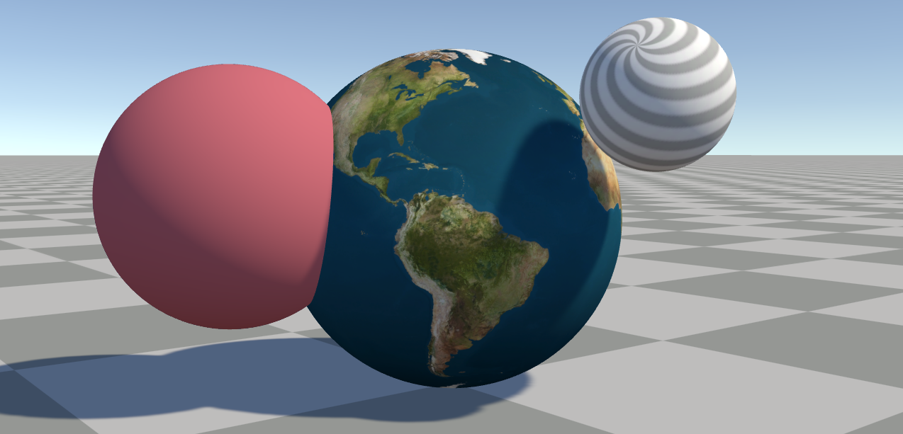
Put that all together with some basic lighting and you go something like this:


Texturing a Sphere
Well, that'southward not too exciting. We should put a texture on it. For that we need UVs, and luckily those are pretty easy for a sphere.
Equirectangular UVs
Lets slap an equirectangular texture on this thing. For that we merely need to feed the normal direction into an atan2() and an acos() and we go something similar this:
            float2 uv = float2(
              // atan returns a value between -pi and pi
              // so we split up past pi * 2 to get -0.5 to 0.5
              atan2(normal.z, normal.x) / (UNITY_PI * 2.0),
              // acos returns 0.0 at the top, pi at the lesser
              // so nosotros flip the y to align with Unity'southward OpenGL mode
              // texture UVs so 0.0 is at the lesser
              acos(-normal.y) / UNITY_PI
);            fixed4 col = tex2D(_MainTex, uv);

And wait at that we've got a perfectly … await. What's this!?

That'south a UV seam! How do we have a UV seam? Well, that comes downwards to how GPUs calculate mip level for mip maps.
Unseamly
GPUs calculate the mip level by what are known equally screen space partial derivatives. Roughly speaking, this is the corporeality a value changes from one pixel to the ane next to it, either above or below. GPUs tin can calculate this value for each set of 2x2 pixels, so the mip level is decide by how much the UVs change with each of these 2x2 "pixel quads". And when we're calculating the UVs hither, the atan2() suddenly jumps from roughly 0.5 to roughly -0.5 between ii pixels. That makes the GPU think the entire texture is beingness displayed between those two pixel. And thus it uses the absolutely smallest mip map information technology has in response.
So how do we work around this? Why by disabling the mip maps of course!
No no no! We admittedly do not practice that. Simply that'due south the usual solution you lot'll observe to most mip map related issues. (As yous may accept seen me complain about elsewhere.) Instead a solution was nicely presented by Marco Tarini.
The thought is to utilise ii UV sets with the seams in different places. And for our specific example, the longitudinal UVs calculated by the atan2() are already a -0.5 to 0.5 range, so all nosotros demand is a frac() to get them into a 0.0 to one.0 range. And so use those aforementioned partial derivatives to pick the UV set with the least alter. The magical function fwidth() gives u.s. how much the value is changing in whatever screen space direction.
            // -0.five to 0.v range
float phi = atan2(worldNormal.z, worldNormal.x) / (UNITY_PI * 2.0);
// 0.0 to ane.0 range
float phi_frac = frac(phi);            float2 uv = float2(
              // uses a small bias to adopt the commencement 'UV set up'
              fwidth(phi) < fwidth(phi_frac) - 0.001 ? phi : phi_frac,
              acos(-worldNormal.y) / UNITY_PI
);
And now we accept no more seam!

* edit: It's come up to my attending that this technique may simply piece of work properly when using Direct3D, integrated Intel GPUs, or (some?) Android OpenGLES devices. The fwidth() function when using OpenGL on desktop may run using college accuracy derivatives than used by the GPU to determine mip levels meaning the seam volition still be visible. Metal is guaranteed to e'er run at a higher accuracy. Vulkan tin can exist forced to run at the lower accuracy by using coarse derivative functions, but as of writing this Unity doesn't seems to properly transpile coarse or fine derivatives. I wrote a follow upwardly with some alternate solutions here:
Alternative you could just apply a cube map instead. Unity can convert an imported equirectangular texture into a cube map for you. But that means you loose out on anisotropic filtering. The UVW for a cube map texture sample is essentially simply the sphere's normal. You practise need to flip at least the x or z centrality though, because cube maps are assumed to be viewed from the "inside" of a sphere and here we desire it to map to the exterior.
Crunchy Edges (aka Derivatives Strike Over again)
At this point if we compare the raytraced sphere shader we accept with an bodily high poly mesh sphere using the same equirectangular UVs, yous may notice something else odd. It looks like there's an outline around the raytraced sphere that the mesh does not accept. A really aliased outline.

The crusade is our pesky derivatives again. There'due south one more UV seam we missed! On a mesh, derivatives are calculated per pixel quad, per triangle. In fact, if a triangle only touches a single pixel of one of those 2x2 pixel quads, the GPU nevertheless runs the fragment shader for all four pixels! The advantage of this is it tin accurately calculate plausible derivatives which prevents this trouble on a real mesh. But we don't have a good UV outside of the sphere, the role just returns a constant -1.0 on a miss, so we have artificial UVs outside of the sphere. We tin can see this clearly if you comment out the clip() and outDepth lines in the shader.

What we want is for the UVs to be something close to the value at the visible edge of the sphere, or maybe just past the edge. That's surprisingly complicated to calculate. But we can get something reasonably shut past finding the closest betoken on a ray to the sphere heart. At the exact sphere edge, this is 100% accurate, simply it starts to curve towards the camera slightly as you lot get farther away from the sphere. Simply this is cheap and good plenty to go rid of the problem and is almost indistinguishable from a fully correct set.

Even better, we can utilise this fix by replacing the ray length with a single dot() when the sphere intersection function returns a -1.0. A super ability of the dot product of 2 vectors is, if at to the lowest degree one vector is normalized, the output is the magnitude other vector is along the direction of the normalized vector. This is great for getting how far away something is in a certain direction, like how far the camera is from the sphere's pivot forth the view ray.
            // same sphere intersection function
bladder rayHit = sphIntersect(rayOrigin, rayDir, float4(0,0,0,0.5));
// clip if -i.0 to hide sphere on miss
clip(rayHit);
// dot product gets ray length at position closest to sphere
rayHit = rayHit < 0.0 ? dot(rayDir, spherePos - rayOrigin) : rayHit; 


Object Calibration & Rotation
And so that'due south all going well, but what if we want to to make a bigger sphere or rotate it? Nosotros can move the mesh position around and the sphere tracks with it, only everything else is ignored.
We could change the sphere radius manually, but so y'all'd have to manually continue the mesh you lot're using in sync. So it'd exist easier to extract the calibration from the object transform itself. And nosotros could apply an capricious rotation matrix, but again it'd be manner easier if we could only utilise the object transform.
Or nosotros could do something even easier and do the raytracing in object space! This comes with a few other benefits nosotros'll become into. But before that nosotros desire to add together a few lines to our shader code. First nosotros want to use the unity_WorldToObject matrix to transform the ray origin and ray direction into object space in the vertex shader. In the fragment shader, we no longer demand to get the world space object position from the transform since the sphere can now merely be at the object'south origin.
            // vertex shader
float3 worldSpaceRayDir = worldPos - _WorldSpaceCameraPos.xyz;
// only desire to rotate and scale the dir vector, so west = 0
o.rayDir = mul(unity_WorldToObject, float4(worldSpaceRayDir, 0.0));
// need to utilize total transform to the origin vector
o.rayOrigin = mul(unity_WorldToObject, float4(_WorldSpaceCameraPos.xyz, i.0));            // fragment shader
float3 spherePos = float3(0,0,0);
With this alter lone, you tin now rotate and scale the game object and the sphere scales and rotates as yous would expect. It even supports non-uniform scaling! Just remember that all of those "earth space" positions in the shader are now in object infinite. And then we need to transform the normal and sphere surface position to world space. Just be sure to use the object space normal for the UVs.
            // now gets an object space surface position instead of globe space
float3 objectSpacePos = rayDir * rayHit + rayOrigin;            // withal need to normalize this in object infinite for the UVs
float3 objectSpaceNormal = normalize(objectSpacePos);            float3 worldNormal = UnityObjectToWorldNormal(objectSpaceNormal);
float3 worldPos = mul(unity_ObjectToWorld, float4(objectSpacePos, ane.0));

Other advantages are better overall precision, as using world infinite for everything can cause some precision issues when getting far away from the origin. Those are at least partially avoided when using object space. Information technology besides ways we can remove the usage of spherePos in several places since information technology'southward all zeros, simplifying the code a bit.
Using a Quad
So far we've been using a cube mesh for all of this. At that place are some minor benefits to using a cube for some utilize cases, but I promised a quad in the title of this commodity. Also because really at that place's no good reason to use an unabridged cube for a sphere. At that place's a lot of wasted infinite effectually the sides where we're paying the cost of rendering the sphere where nosotros know it'due south not going to exist. Especially the default Unity cube which has 24 vertices! Why also waste calculating the actress 20 vertices?
Billboard Shader
There are several examples of billboard shaders out there. The basic thought for all of them is you ignore the rotation (and scale!) of the object's transform and instead align the mesh to face the camera in some mode.
View Facing Billboard
Probably the virtually common version of this is a view facing billboard. This is done by transforming the pivot position into view infinite and adding the vertex offsets to the view space position. This is relatively cheap to do. Only remember to update the ray direction to match.
            // go object's world space pivot from the transform matrix
float3 worldSpacePivot = unity_ObjectToWorld._m03_m13_m23;            // transform into view infinite
float3 viewSpacePivot = mul(UNITY_MATRIX_V, float4(worldSpacePivot, 1.0));            // object space vertex position + view pivot = billboarded quad
float3 viewSpacePos = 5.vertex.xyz + viewSpacePivot;            // calculate the object space ray dir from the view infinite position
o.rayDir = mul(unity_WorldToObject,
              mul(UNITY_MATRIX_I_V, float4(viewSpacePos, 0.0))
);            // use project matrix to get clip space position
o.pos = mul(UNITY_MATRIX_P, float4(viewSpacePos, one.0));
Nonetheless, if we only add the above code to our shader, there'due south something not quite right with the sphere. It's getting clipped on the edges, especially when the sphere is to the side or close to the camera.

This is because the quad is a apartment plane, and the sphere is not. A sphere has some depth. Due to perspective the volume of the sphere will cover more of the screen than the quad does!

A solution to this you might use is to scale the billboard up by some arbitrary amount. Just this doesn't fully solve the problem as you take to scale the quad upwards quite a bit. Peculiarly if you can get close to the sphere or have a very wide FOV. And this partially defeats the purpose of using a quad over a cube to begin with. Indeed more pixels are now rendering empty space than earlier with fifty-fifty relatively minor scale increases compared to the cube.

Camera Facing Billboard
Luckily, nosotros tin can do a lot better. A partial fix is to utilize a photographic camera facing billboard instead of a view facing billboard and pull the quad towards the camera slightly. The difference between view facing and photographic camera facing billboards is a view facing billboard is aligned with the direction the view is facing. A camera facing billboard is facing the camera'south position. The departure can exist subtle, and the code is a scrap more than circuitous.
Instead of doing things in view infinite, nosotros instead demand to construct a rotation matrix that rotates a quad towards the camera. This sounds scarier than it is. Yous just need to get the vector that points from the object position to the photographic camera, the forward vector, and utilise cross products to become the up and right vectors. Put those three vectors together and you take yourself a rotation matrix.
            float3 worldSpacePivot = unity_ObjectToWorld._m03_m13_m23;            // get-go betwixt pivot and photographic camera
float3 worldSpacePivotToCamera = _WorldSpaceCameraPos.xyz - worldSpacePivot;            // camera up vector
// used equally a somewhat capricious starting up orientation
float3 up = UNITY_MATRIX_I_V._m01_m11_m2;            // forward vector is the normalized beginning
// this it the direction from the pivot to the camera
float3 frontward = normalize(worldSpacePivotToCamera);            // cross product gets a vector perpendicular to the input vectors
float3 right = normalize(cross(forward, upwards));            // some other cross product ensures the upward is perpendicular to both
upward = cross(correct, forrad);            // construct the rotation matrix
float3x3 rotMat = float3x3(right, upward, forward);            // the above rotate matrix is transposed, significant the components are
// in the wrong society, but we can piece of work with that by swapping the
// order of the matrix and vector in the mul()
float3 worldPos = mul(5.vertex.xyz, rotMat) + worldSpacePivot;            // ray direction
float3 worldRayDir = worldPos - _WorldSpaceCameraPos.xyz;
o.rayDir = mul(unity_WorldToObject, float4(worldRayDir, 0.0));            // clip infinite position output
o.pos = UnityWorldToClipPos(worldPos);

This is better, but even so not skillful. The sphere is all the same clipping the edges of the quad. Actually, all the four edges now. At least it'southward centered. Well, nosotros forgot to movement the quad toward the photographic camera! Technically we could too calibration the quad by an arbitrary amount too, but lets come back to that signal.
float3 worldPos = mul(float3(v.vertex.xy, 0.3), rotMat) + worldSpacePivot; We're ignoring the z of the quad and adding a small (arbitrary) get-go to pull it towards the camera. The advantage of this pick vs an arbitrary scaling is it should stay more closely confined to the bounds of the sphere when further abroad, and scale when closer only due to the perspective alter, only like the sphere itself. It only starts to embrace significantly more screen space than needed when actually shut. I chose 0.three in the to a higher place example because it was a skilful residue of non roofing too much of the screen when close past, while even so covering all of the viewable sphere until you're really, actually close.

You lot know, you lot could probably figure the exact value to use to pull or calibration the quad for a given altitude from the sphere with a fleck of math …
Perfect Perspective Billboard Scaling
Expect! Nosotros tin can figure out the value using a bit of math! We can get the verbal size the quad needs to exist at all camera distances from the sphere. Merely needs some bones high schoolhouse math!
We can calculate the angle betwixt the photographic camera to pivot vector and camera to visible border of the sphere. In fact it's always a correct triangle with the 90 caste corner at the sphere'due south surface! Recollect your sometime friend SOHCAHTOA? We know the distance from the camera to the pivot, that's the hypotenuse. And we know the radius of the sphere. From that nosotros can calculate the base of operations of the right angle triangle formed from projecting that angle to the quad'south plane. With that we can scale the quad instead of modifying the 5.vertex.z.
            // get the sine of the right triangle with the hypotenuse being the // sphere pivot altitude and the opposite using the sphere radius
float sinAngle = 0.five / length(viewOffset);            // catechumen to cosine
bladder cosAngle = sqrt(i.0 - sinAngle * sinAngle);            // convert to tangent
float tanAngle = sinAngle / cosAngle;            // those previous ii lines are the equivalent of this, but faster
// tanAngle = tan(asin(sinAngle));            // go the opposite face of the right triangle with the 90 degree
// angle at the sphere pin, multiplied by ii to go the quad size
float quadScale = tanAngle * length(viewOffset) * two.0;            // scale the quad by the calculated size
float3 worldPos = mul(float3(v.vertex.xy, 0.0) * quadScale, rotMat) + worldSpacePivot;

Bookkeeping for Object Scale
At the get-go of this we converted everything in to using object space so we could trivially support rotation and calibration. We still support rotation, since the quad'south orientation doesn't really thing. But the quad doesn't calibration with the object'southward transform similar the cube did. The easiest fix for this is to extract the calibration from the centrality of the transform matrix and multiply the radius we're using by the max calibration.
            // become the object scale
float3 calibration = float3(
              length(unity_ObjectToWorld._m00_m10_m20),
              length(unity_ObjectToWorld._m01_m11_m21),
              length(unity_ObjectToWorld._m02_m12_m22)
);
float maxScale = max(abs(scale.x), max(abs(scale.y), abs(scale.z)));            // multiply the sphere radius past the max scale
bladder maxRadius = maxScale * 0.5;            // update our sine adding using the new radius
float sinAngle = maxRadius / length(viewOffset);            // do the rest of the scaling lawmaking
Now you tin can uniformly calibration the game object and the sphere will still remain perfectly bound by the quad.
Ellipsoid Premises?
It should as well be possible to summate the exact premises of an ellipsoid, or non-uniformly scaled sphere. Unfortunately that's starting to go a bit more than difficult. So I'1000 not going to put the try into solving that problem now. I'll go out this as "an exercise for the reader." (Aka, I have no thought how to exercise it.)
Frustum Culling
One additional problem with using a quad is Unity'southward frustum culling. It has no thought that the quad is being rotated in the shader, then if the game object is rotated so it's being viewed border on information technology may get frustum culled while the sphere should still be visible. The fix for this would be to employ a custom quad mesh that's had its bounds manually modified from c# code to be a box. Alternatively you tin can employ a quad mesh with one vertex pushed forward and one back by 0.five on the z axis. And we're already flatten the mesh in the shader by replacing v.vertex.z with 0.0.
Shadow Casting
So now we have a nicely rendered sphere on a quad that is lit, textured, and can be moved, scaled, and rotated around. So lets make it cast shadows! For that nosotros'll need to brand a shadow pulley pass in our shader. Luckily the same vertex shader can be reused for both passes, since all it does is create a quad and pass along the ray origin and management. And those of form will be exactly the aforementioned for the shadows as information technology is for the photographic camera, right? Then the fragment shader really merely needs to output the depth, and so yous can delete all that pesky UV and lighting code.
Oh.
The ray origin and management need to be coming from the light, non the camera. And the value we're using for the ray origin is always the current camera position, not the light. The good news is that's not hard to fix. We tin can supercede any usage of _WorldSpaceCameraPos with UNITY_MATRIX_I_V._m03_m13_m23 which gets the current view's world position from the inverse view matrix. Now equally long as the shadows are rendered with perspective projections it should all piece of work!
Oh. Oh, no.
Directional shadows use an orthographic project.
Orthographic Pain
The nice thing with perspective project and ray tracing is the ray origin is where the camera is. That's really easy to get, fifty-fifty for capricious views, as shown to a higher place. For orthographic projections the ray direction is the forward view vector. That'due south like shooting fish in a barrel plenty to go from the inverse view matrix over again.
            // forwards in view infinite is -z, so we want the negative vector
float3 worldSpaceViewForward = -UNITY_MATRIX_I_V._m02_m12_m22;
Just how practise we get the orthographic ray origin? If yous effort and search online you'll probably come across a bunch of examples that employ a c# script to get the changed project matrix. Or abuse the current unity_OrthoParams which has data about the orthographic projection'due south width and pinnacle. Yous can so utilize the prune space position to reconstruct the near view plane position the ray is originating from. The trouble with these approaches is they're all getting the camera's orthographic settings, not the current light's. And then instead we have to calculate the inverse matrix in the shader!
            float4x4 inverse(float4x4 k) {
              bladder n11 = m[0][0], n12 = m[1][0], n13 = thou[ii][0], n14 = m[iii][0];
              float n21 = g[0][1], n22 = m[1][1], n23 = one thousand[2][ane], n24 = m[3][1];
              bladder n31 = g[0][two], n32 = chiliad[i][2], n33 = grand[2][ii], n34 = yard[3][two];
              float n41 = m[0][3], n42 = m[1][3], n43 = one thousand[two][3], n44 = m[3][3];                          float t11 = n23 * n34 * n42 - n24 * n33 * n42 + n24 * n32 * n43 - n22 * n34 * n43 - n23 * n32 * n44 + n22 * n33 * n44;            // ... hold upwardly, how many more lines are there of this?!
Ok, lets not do that. Those are just the first few lines of a >xxx line function of increasing length and complication. There's got to exist a better way.
The Nearly View Plane
As it turns out, you don't need any of that. We don't actually need the ray origin to be at the near airplane. The ray origin really just needs to be the mesh's position pulled dorsum along the forward view vector. Just far enough to make certain information technology's not starting inside the volume of the sphere. At least assuming the camera itself isn't already inside the sphere. And a "near plane" at the camera's position instead of the actual near plane totally fits that bill.
Nosotros already know the world position of the vertex in the vertex shader. Then we could transform the world position into view space. Zero out the viewSpacePos.z, and transform back into world space. That results in a usable ray origin for an orthographic projection!
            // transform world space vertex position into view space
float4 viewSpacePos = mul(UNITY_MATRIX_V, float4(worldPos, 1.0));            // flatten the view space position to be on the camera plane
viewSpacePos.z = 0.0;            // transform back into world space
float4 worldRayOrigin = mul(UNITY_MATRIX_I_V, viewSpacePos);            // orthographic ray dir
float3 worldRayDir = worldSpaceViewForward;            // and to object infinite
o.rayDir = mul(unity_WorldToObject, float4(worldRayDir, 0.0));
o.rayOrigin = mul(unity_WorldToObject, worldRayOrigin);
And really nosotros don't even need to do all that. Call up that super ability of the dot() I mentioned in a higher place? We only need the camera to vertex position vector and the normalized forward view vector. We already take the photographic camera to vertex position vector, that's the original perspective globe space ray direction. And we know the forward view vector by extracting information technology from the matrix mentioned to a higher place. Conveniently this vector comes already normalized! So nosotros tin remove ii of the matrix multiplies in the above lawmaking and practice this instead:
            float3 worldSpaceViewPos =               UNITY_MATRIX_I_V._m03_m13_m23;
float3 worldSpaceViewForward = -UNITY_MATRIX_I_V._m02_m12_m2;            // originally the perspective ray dir
float3 worldCameraToPos = worldPos - worldSpaceViewPos;            // orthographic ray dir
float3 worldRayDir = worldSpaceViewForward * -dot(worldCameraToPos, worldSpaceViewForward);            // orthographic ray origin
float3 worldRayOrigin = worldPos - worldRayDir;            o.rayDir = mul(unity_WorldToObject, float4(worldRayDir, 0.0));
o.rayOrigin = mul(unity_WorldToObject, float4(worldRayOrigin, 1.0));
* At that place is one minor caveat. This does not work for oblique projections (aka a sheared orthographic projection). For that you really do demand the inverse projection matrix. Sheared perspective projections are fine though!
Light Facing Billboard
Remember how nosotros're doing photographic camera facing billboards? And that fancy math to calibration the quad to account for the perspective? We don't need whatever of that for an orthographic projection. Just demand to practice view facing billboarding and calibration the quad by only the object transform'south max scale. Notwithstanding maybe lets non delete all of that code quite yet. We tin can use the existing rotation matrix construction equally is, just alter the forward vector to exist the negative worldSpaceViewForward vector instead of the worldSpacePivotToCamera vector.
A Point of Perspective
In fact now might be a good time to talk about how the spot lights and point lights use perspective projection. If we want to back up directional lights, spot lights, and point low-cal shadows we're going to demand to back up both perspective and orthographic in the same shader. Unity also uses this pass to return the camera depth texture. This means we need to detect if the electric current projection matrix is orthographic or not and choose between the two paths.
Well, nosotros can find out what kind of projection matrix nosotros're using by checking a specific component of it. The very last component of a projection matrix will be 0.0 if it's a perspective projection matrix, and will exist 1.0 if information technology's an orthographic projection matrix.
            bool isOrtho = UNITY_MATRIX_P._m33 == one.0;            // billboard code
float3 forward = isOrtho ? -worldSpaceViewForward : normalize(worldSpacePivotToCamera);
// do the residue of the billboard lawmaking            // quad scaling code
float quadScale = maxScale;
if (!isOrtho)
{
              // exercise that perfect scaling lawmaking
}            // ray direction and origin code
float3 worldRayOrigin = worldSpaceViewPos;
float3 worldRayDir = worldPos - worldSpaceRayOrigin;
if (isOrtho)
{
              worldRayDir = worldSpaceViewForward * -dot(worldRayDir, worldSpaceViewForward);
              worldRayOrigin = worldPos - worldRayDir;
}            o.rayDir = mul(unity_WorldToObject, float4(worldRayDir, 0.0));
o.rayOrigin = mul(unity_WorldToObject, float4(worldRayOrigin, 1.0));            // don't worry, I'll show the whole vertex shader after
And now nosotros accept a vertex office that can correctly handle both orthographic and perspective projection! And zilch needs to modify in the fragment shader to business relationship for this. Oh, and we really can use the same role for both the shadow caster and forward lit pass. And at present you tin can employ an orthographic camera likewise!
Shadow Bias
Now if yous'd been following along, you'll have a shadow caster pass outputting depth. Just we're not calling whatsoever of the usual functions a shadow caster usually has for applying offset. At the moment this isn't obvious since nosotros're not cocky shadowing nevertheless, but it'll exist a trouble if we don't fix it.
We're not going to use the built in TRANSFER_SHADOW_CASTER_NORMALOFFSET(o) macro for the vertex shader for this since nosotros need to do the bias in the fragment shader. Luckily, there's another do good to doing the raytracing in object space. The beginning part that the shadow caster vertex shader macro calls assumes the position being passed to it is in object space! I mean, that makes sense, since it assumes information technology's working on the starting object space vertex position. Only this means nosotros tin use the biasing functions the shadow pulley macros call directly using the position we've raytraced and they'll just work!

            Tags { "LightMode" = "ShadowCaster" }            ZWrite On ZTest LEqual            CGPROGRAM
#pragma vertex vert
#pragma fragment frag_shadow            #pragma multi_compile_shadowcaster            // yes, I know the vertex function is missing            fixed4 frag_shadow (v2f i,
              out float outDepth : SV_Depth
              ) : SV_Target
{
              // ray origin
              float3 rayOrigin = i.rayOrigin;                          // normalize ray vector
              float3 rayDir = normalize(i.rayDir);                          // ray sphere intersection
              float rayHit = sphIntersect(rayOrigin, rayDir, float4(0,0,0,0.5));                          // above function returns -1 if there's no intersection
              clip(rayHit);                          // calculate object space position
              float3 objectSpacePos = rayDir * rayHit + rayOrigin;                          // output modified depth
              // yes, we pass in objectSpacePos as both arguments
              // second one is for the object space normal, which in this instance
              // is the normalized position, just the function transforms it
              // into world space and normalizes information technology so we don't accept to
              float4 clipPos = UnityClipSpaceShadowCasterPos(objectSpacePos, objectSpacePos);
              clipPos = UnityApplyLinearShadowBias(clipPos);
              outDepth = clipPos.z / clipPos.west;                          return 0;
}
ENDCG
That it. And this works for every shadow caster variant.* Directional light shadows, spot lite shadows, betoken calorie-free shadows, and the camera depth texture! You know, should we e'er want to back up multiple lights…
* I didn't add support for GLES 2.0 betoken low-cal shadows. That requires outputting the distance from the light as the shadow caster pass'due south color value instead of just a difficult coded 0 . Information technology's not besides hard to add together, but it makes the shader a fleck messier with a few #if and special case data we'd demand to calculate. So I didn't include it.
* edit: I forgot 1 thing for handling depth on OpenGL platforms. Clip infinite z for OpenGL is a -westward to +w range, and then you need to do ane extra step to convert that into the 0.0 to 1.0 range needed for the fragment shader output depth.
            #if !defined(UNITY_REVERSED_Z) // basically only OpenGL
outDepth = outDepth * 0.five + 0.5;
0 Response to "how to draw sphere in 3d"
Post a Comment